University of Tennessee in Chattanooga - Spring 2023
Christopher Harmon, Thomas Clemmons, Tahj Taylor, Nate Hawkins, Deimer Ordonez Gomez, John Lazenby
In the world of robotics, integrating various components to create a cohesive system is a common challenge that engineers and designers face. As technology continues to advance, the need for custom PCB designs has become increasingly prevalent. We recognized the importance of a custom PCB design for our robotics project due to the integration of various components, which required specific electrical connections and high current handling capabilities.
To achieve our custom PCB design, we used EasyEDA, an online PCB design tool, to create the schematics and layout for our PCB. We then used PCBWay, a PCB printing service, to manufacture the final product. This process allowed us to customize our PCB to meet the unique requirements of our project.
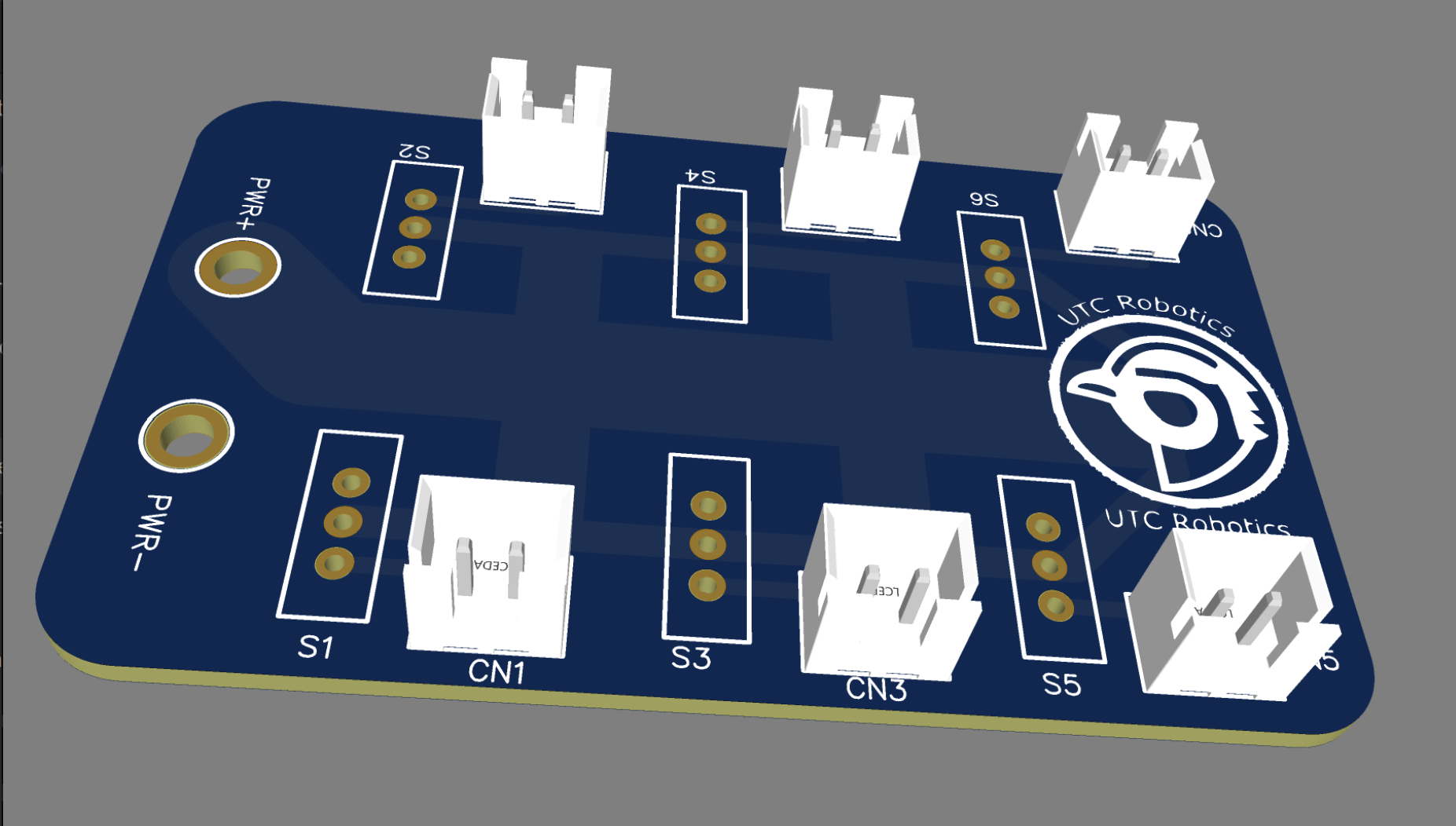
Our initial design was a small business card sized PCB that provided six 5 or 12 volt and GND connections(version 1.0). This design allowed us to test the capabilities of our PCB before moving on to a more complex design. We knew that we needed to ensure that the traces on the PCB were wide enough to handle the high current that our components required. Specifically, we needed the PCB to handle a sustained current of 12 amps and a peak current of 30 amps, so a minor change was made to the trace width and pattern(version 1.1).
PCB Design Version 1.0
PCB Design Version 1.1
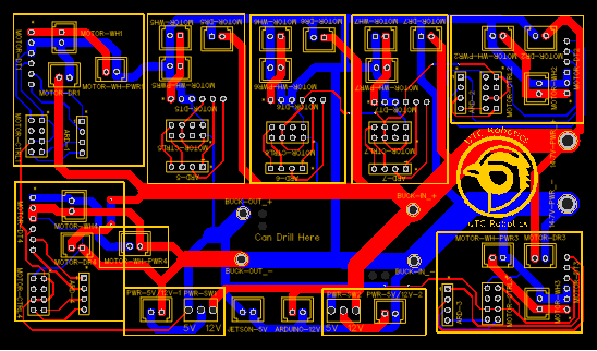
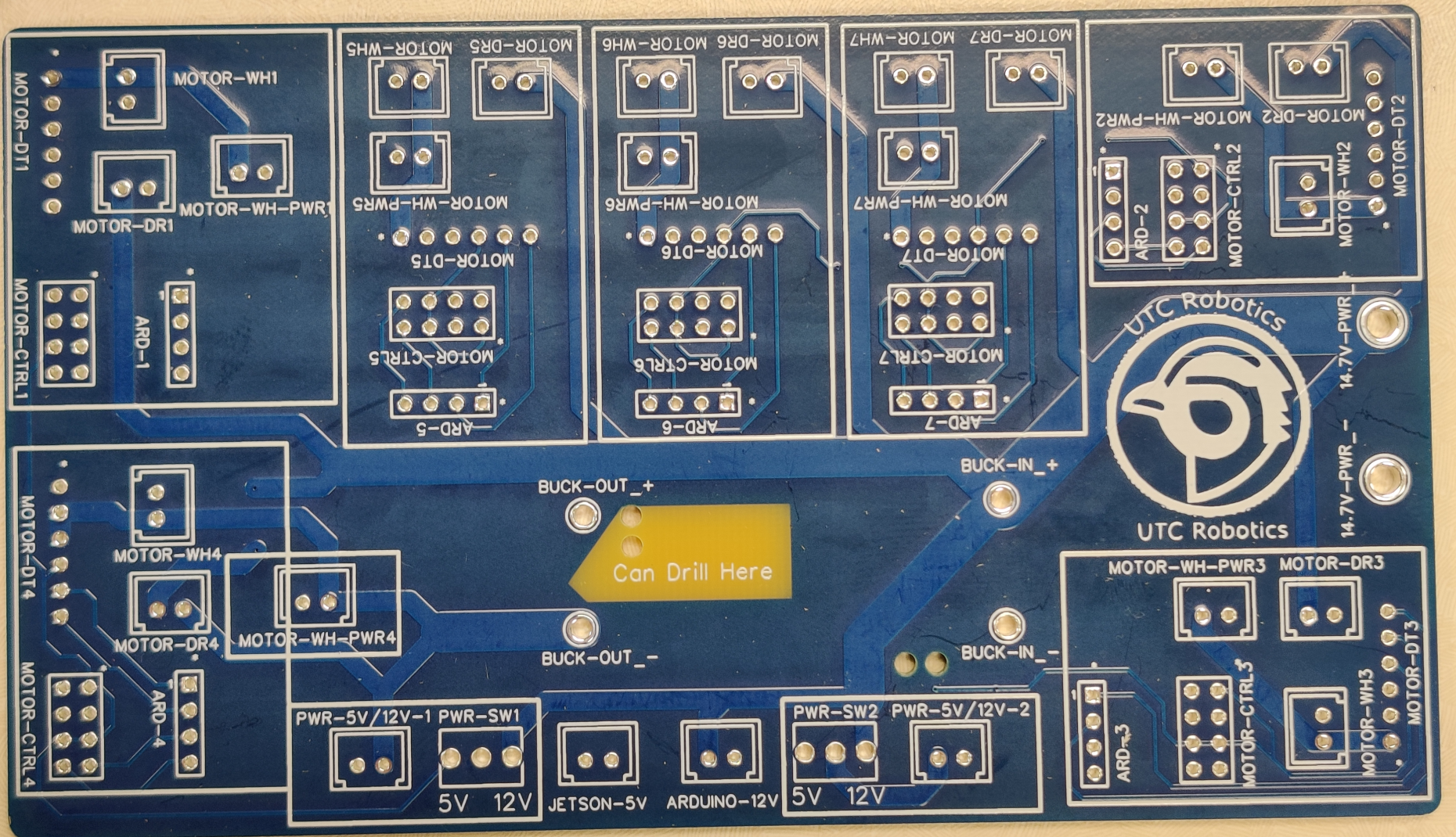
PCB Design Version 2.0 Front
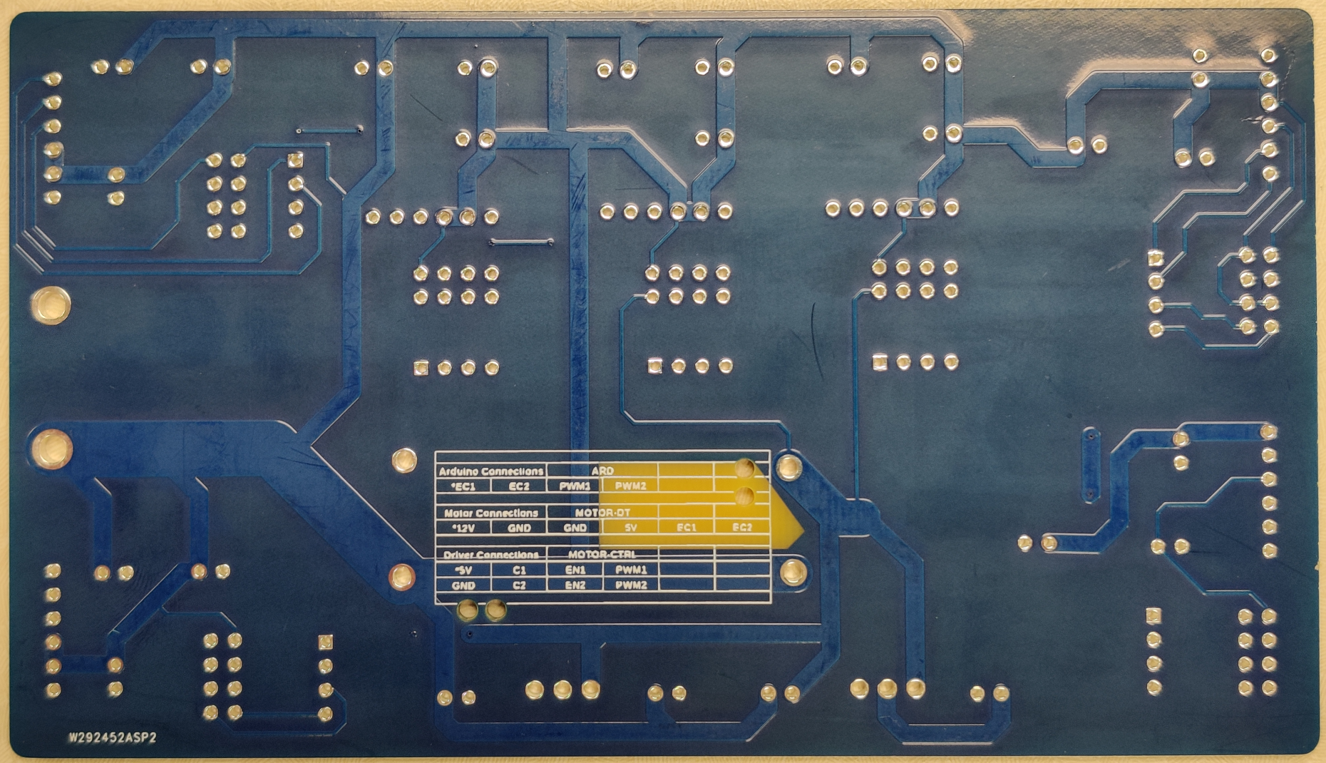
PCB Design Version 2.0 Back
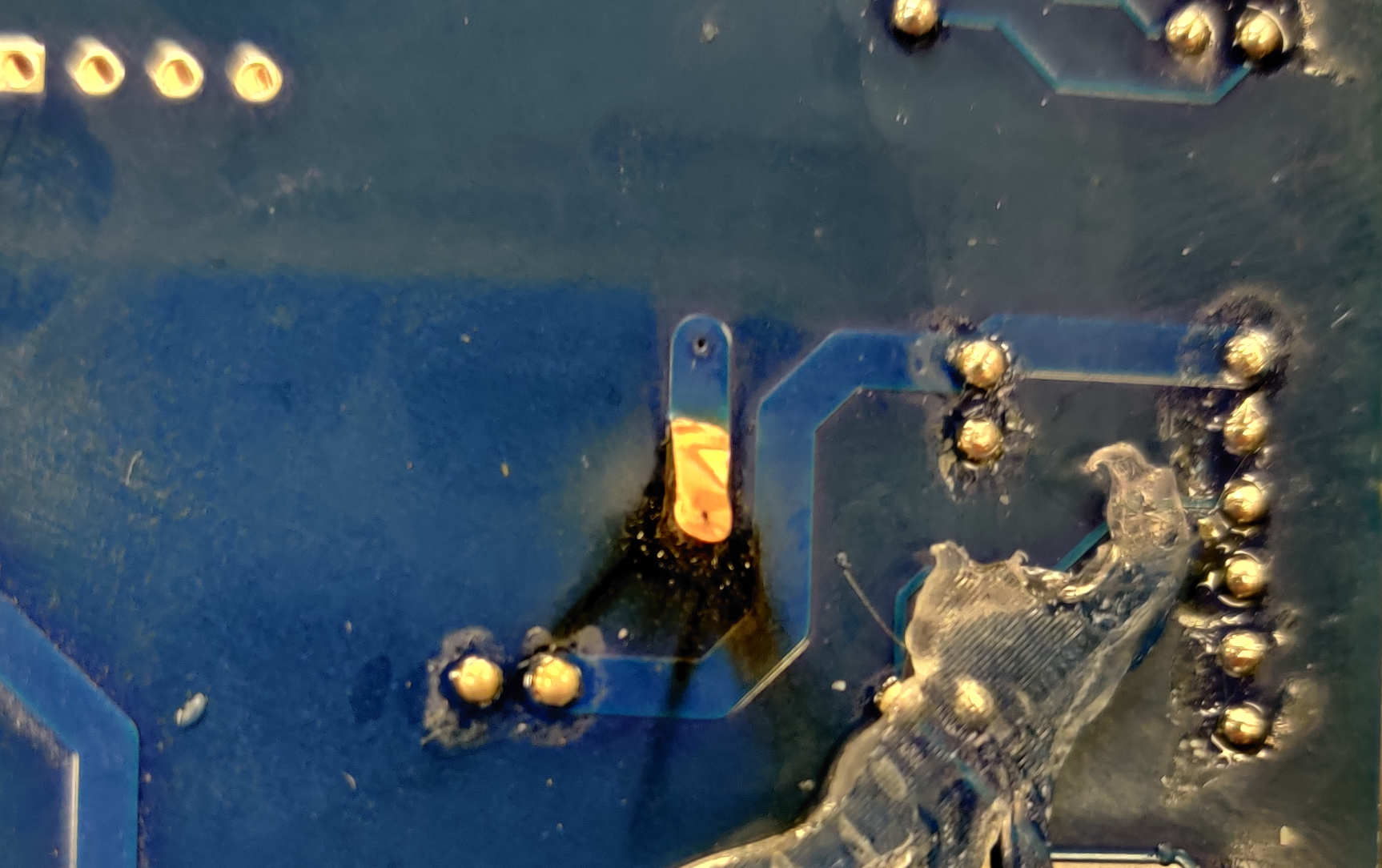
2.0 Failure
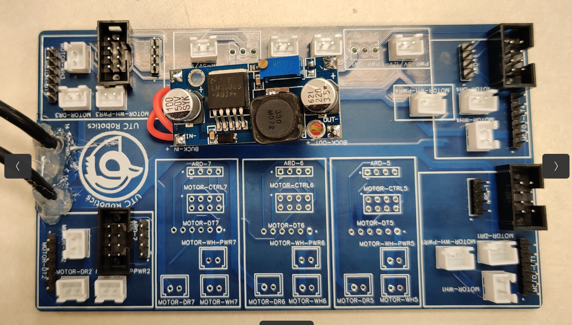
PCB Design Version 2.1
Version 2 of our custom PCB was a significant step forward from our initial design. We integrated full 12 volt distribution and 5 volt distribution, along with data pins. The data pins involved 5 volt logic lines that enabled the motor driver pins, provided 5 volt power to the motor encoders. This version also provided 5 volts to power the Jetsonas well as 12 power to the motors and Arduino if needed.
While version 2 of our PCB was a major improvement, we soon discovered a flaw that required a minor redesign. The flaw was an accidental PCB trace between the negative motor line and GND. This problem became apparent when we instructed the motor controller to go in reverse. The negative motor voltage became positive, causing a 16-volt short to ground.
This flaw not only prevented the proper operation of the motors, it was also a significant concern as it could cause damage to our components and even pose a safety risk. However, thanks to the large rtaces in our design, we were able to quickly identify the issue and implement a solution. Using a rotory tool we made a minor redesign that separated the negative motor line from the GND connection and used short lenghs of wire to reconnect certain traces, ensuring that we avoided any potential shorts in the future.
The custom PCB design was an essential component of our project, and without it, we would not have been able to integrate our various components effectively. Future designs will involve correcting the 12 volt short flaw include a single data bus connecting the distribution board to an Arduino Mega shield making connections easier and simplier.
Custom PCB designs are a crucial component of modern robotics, and our project is a prime example of their importance in ensuring the effective integration of various components.